RWK-35 Recloser Controller | ANSI C37.60 Protection & DNP3.0

Key attributes
| Brand | Rw Energy |
| Model NO. | RWK-35 Recloser Controller | ANSI C37.60 Protection & DNP3.0 |
| Rated voltage | 230V ±20% |
| Rated frequency | 50/60Hz |
| Electric energy consumption | ≤5W |
| Version | V2.3.3 |
| Series | RWK-35 |
Description
RWK-35 is an intelligent medium voltage controller designed for overhead line grid monitoring and protection. It pairs with CW(VB) type vacuum circuit breakers to deliver automatic monitoring, fault analysis, and event recording.
This unit provides safe line switching of faults and automatic power recovery, significantly reducing outage duration and improving SAIDI/SAIFI metrics. Suitable for up to 35kV outdoor switchgear including vacuum, oil, and gas circuit breakers, the RWK-35 integrates line protection, control, measurement, and monitoring of voltage and current signals in a single outdoor automation device.
RWK-35 is an automatic management unit supporting single way, multi-way, ring network, and two-power sourcing topologies, with full voltage and current signal acquisition.
Competitive Benchmarking
The RWK-35 is designed as a direct alternative to established international recloser controller platforms such as Eaton Form 6 / Form 7 and ABB RER615, offering equivalent ANSI C37.60 protection functionality with enhanced communication flexibility and SEF sensitivity.
Compliance & Certification
-
Fully compliant with ANSI C37.60 (recloser requirements) and IEC 60255 (measuring relays and protection equipment) series standards.
-
Designed in accordance with DL/T 721-2000 Class IV.
Communication
The RWK-35 supports comprehensive multi-protocol communication for seamless SCADA and DMS integration.
-
Protocols: DNP3.0 (over Ethernet/Serial), IEC 60870-5-101/104, Modbus RTU, IEC 61850 MMS/GOOSE readiness
-
Interfaces: RS485, RJ45 (Ethernet), RS232, optical fiber, GPRS/CDMA, WiFi, power line carrier
-
PC Software: RWK381HB-V2.1.3 with editable and queryable information body addresses
-
SCADA Integration: Fully compatible with SCADA systems supporting DNP3.0, IEC 101/104, or Modbus RTU
-
Interoperability: Can access other station premises equipment (TTU, FTU, DTU, etc.)
Protection Relay Functions
ANSI Protection Functions
| Code | Function |
|---|---|
| 79 | Auto Reclose |
| 50P | Instantaneous / Definite-Time Overcurrent (Phase) |
| 51P | Phase Time-Overcurrent (Fast / Delay curves) |
| 50/67P | Directional Phase Overcurrent (Forward / Reverse) |
| 51/67P | Directional Phase Time-Overcurrent (Forward / Reverse) |
| 50G/N | Ground Instantaneous / Definite-Time Overcurrent |
| 51G/N | Ground Time-Overcurrent (Fast / Delay curves) |
| 50/67G/N | Directional Ground Overcurrent (Forward / Reverse) |
| 51/67G/N | Directional Ground Time-Overcurrent (Forward / Reverse) |
| 50SEF | Sensitive Earth Fault — minimum pick-up current down to 200mA (adjustable), supporting high-impedance fault detection — directly comparable to Eaton Form 7 HiZ Protect |
| 50/67SEF | Directional Sensitive Earth Fault (Forward / Reverse) |
| 59/27TN | Earth Fault Protection with 3rd Harmonic Restraint |
| 51C | Cold Load Pickup |
| TRSOTF | Switch-Onto-Fault (SOTF) |
| 81 | Frequency Protection (over/under) |
| 46 | Negative-Sequence Overcurrent |
| 27 | Under Voltage |
| 59 | Over Voltage |
| 59N | Zero-Sequence Over Voltage |
| 25N | Synchronism Check |
| 25/79 | Synchronism Check / Auto Reclose |
| 60 | Voltage Unbalance |
| 32 | Power Direction |
| - | Inrush Restraint: Advanced 2nd Harmonic Blocking: Due to the high peak of asymmetrical inrush current during transformer energization, RWK-35 executes real-time spectral analysis to inhibit protection tripping, ensuring grid stability without compromising fault sensitivity. |
| - | Loss of Phase |
| - | Live Load Block |
| - | High Gas |
| - | High Temperature |
| - | Hotline Protection |
Distributed Generation (DG) Friendly
Built-in ANSI 32 (Power Direction) and ANSI 81 (Frequency) protection to manage bi-directional power flow and provide anti-islanding capability for solar PV and wind grid connections-critical for modern distribution networks with high DER penetration.
Supervision Functions
| Code | Function |
|---|---|
| 74T/CCS | Trip & Close Circuit Supervision |
| 60VTS | VT Supervision |
Control Functions
| Code | Function |
|---|---|
| 86 | Lockout |
| - | Circuit-breaker control (open/close) |
Monitoring Functions
-
Primary / Secondary phase and earth currents
-
Phase currents with 2nd harmonics; earth current with 3rd harmonics
-
Direction, primary/secondary line and phase voltages
-
Apparent power, power factor, real and reactive power
-
Energy and historical energy
-
Max demand and monthly max demand
-
Positive / Negative / Zero sequence voltages and currents
-
Frequency
-
Binary input/output status
-
Trip circuit healthy / failure
-
Time and date
-
Trip, alarm, signal records, counters
-
Wear, outage
Data Storage
-
Event Records
-
Fault Records
-
Measurands
Technical Parameters
Model & System
| Item | RWK-351HBV | RWK-352HBV |
|---|---|---|
| Model | RWK-351HBV | RWK-352HBV |
| Version | V2.3.3 | V2.3.3 |
| Operating Mechanism | Spring mechanism | Magnetic actuator |
| System Language | English | Russian |
| PC Software Language | Chinese Simplified / English / Spanish | Russian |
Power Supply
| Item | Specification |
|---|---|
| Rated Working Voltage | 230V ± 20% |
| Rated Frequency | 50Hz / 60Hz |
| Power Consumption | ≤ 5W |
Power Management I/O
-
1 DC voltage measurement, 1 battery undervoltage alarm, 1 battery active state, 1 battery active control
-
Rated voltage: DC24V, current consumption: ≤10mA
Analog Input
| Item | Specification |
|---|---|
| Current Inputs | 3 phase + 1 earth |
| Rated Current In | 5A or 1A |
| Voltage Input | 1 voltage transformer, 40-120 Vrms |
| Voltage Sensor Inputs | 6 channels, 0-60 Vrms |
Protection & Measurement Accuracy
| Item | Accuracy |
|---|---|
| Current Protection (secondary) | 0.05~50A ≤ ± 3% |
| Zero-Seq Current Protection (secondary) | 0.02~10A ≤ ± 1% |
| Voltage | 10~280V ≤ ± 5% |
Protection Performance
| Item | Value |
|---|---|
| Event Resolution | 2ms |
| Quick-break Trip Time (1.2×In) | <40ms |
| Trip Time Error | ≤1% |
Switching I/O
| Item | Specification |
|---|---|
| DI | 1COM & 10DI, DC24V, ≤2mA |
| Resolution | Minimum 2ms |
| DO Group 1 | 2 groups NO, 230VDC, 120A |
| DO Group 2 | 2 groups NO & NC, 250VAC / 30VDC, 5A(AC) / 3A(DC) |
Communication I/O
| Port | Specification |
|---|---|
| RS232 | 1x DB9, 1200bps~38400bps |
| RS485 | 13-pin terminal + 1x DB9, 1200bps~38400bps |
| Ethernet | 1x RJ45, 10/100Mbps |
EMC & Dielectric
| Item | Specification |
|---|---|
| Insulation Resistance | ≥10MΩ |
| Voltage Surge | 100%, 0.5s |
| HF Interference (Series / Common) | 1.5kVp / 2.5kVp, 1min |
| Transient Pulse | 4.0kVp, 1min |
| Surge Current | 4.0kVp, 1.2/50μs |
| Electrostatic Discharge | 8kV |
| Power Frequency Magnetic Field | 100A/m |
| Damped Oscillatory Magnetic Field | 100A/m |
| Power Frequency Withstand | 2.5kV, 1min |
| Lightning Surge | 5kV, 1.2/50μs |
| Standard | DL/T 721-2000 Class IV |
Working Environment
| Item | Range |
|---|---|
| Ambient Temperature | -25℃~+70℃ |
| Storage Temperature | -40℃~+70℃ |
| Humidity | 5% ~ 100% (non-condensing) |
| Temperature Change Rate | <25℃/h |
| Altitude | 100 ~ 3000m |
Mechanical
| Item | Specification |
|---|---|
| Weight | >10kg |
| Dimensions | 575*420*245mm(Lead acid battery)/ 635*420*245mm(Lithium ion battery) |
| Protection Class | IP55 |
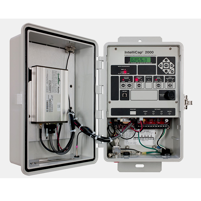
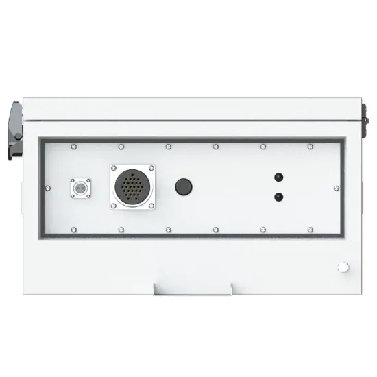
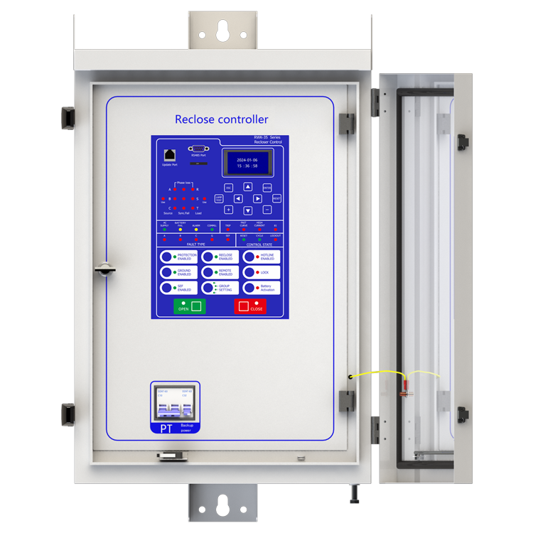
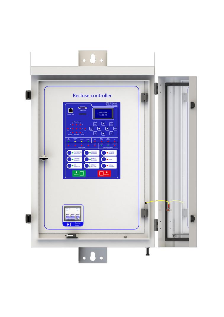
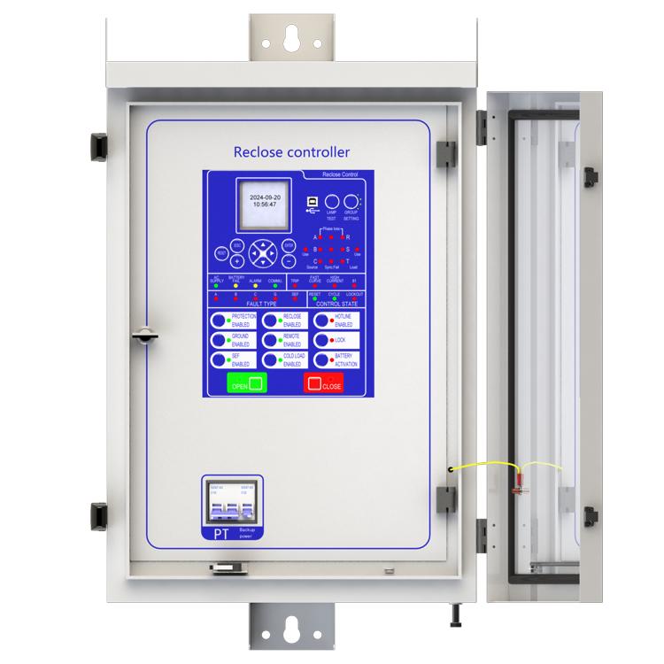
Device structure


Q: Does the RWK-35 support DNP3.0 communication?
A: Yes, the RWK-35 series fully supports the DNP3.0 and IEC 60870-5-104 protocols over RS485 or Ethernet, ensuring seamless integration with existing SCADA and DMS platforms.
Q: Can this controller detect high impedance faults?
A: With its integrated Sensitive Earth Fault (SEF) function (50SEF), the RWK-35 can detect leakage currents as low as 200mA, providing superior protection against high-impedance faults in forested or rural environments.
Ustomization Options
The following optional functions are available:
-
Power supply rated at 110V / 60Hz
-
Cabinet heating / defrosting device
-
Battery upgrade to lithium-ion
-
GPRS communication module
-
1~2 signal indicators
-
1~4 protection pressure plates
-
Second voltage transformer
-
Custom aviation socket signal definition
For detailed customization, please contact our sales team.
Reference Projects for Recloser Controllers
-
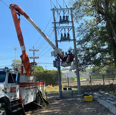 RW Energy Colombia PV Plant 35 kV Recloser Controller Project Case StudyFacing the frequency fluctuation and grid connection challenges of Colombia’s low-inertia photovoltaic power grid, this solution leverages customized recloser control and optimized frequency protection technologies to precisely adapt to the local 60Hz grid standard. It effectively addresses grid fluctuation issues under complex grid connection conditions, delivering a highly reliable and strong anti-interference grid protection solution for photovoltaic power plants and ensuring their stab
Documentation Resource Library Recloser Controllers


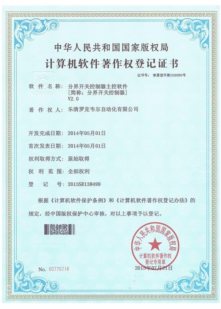
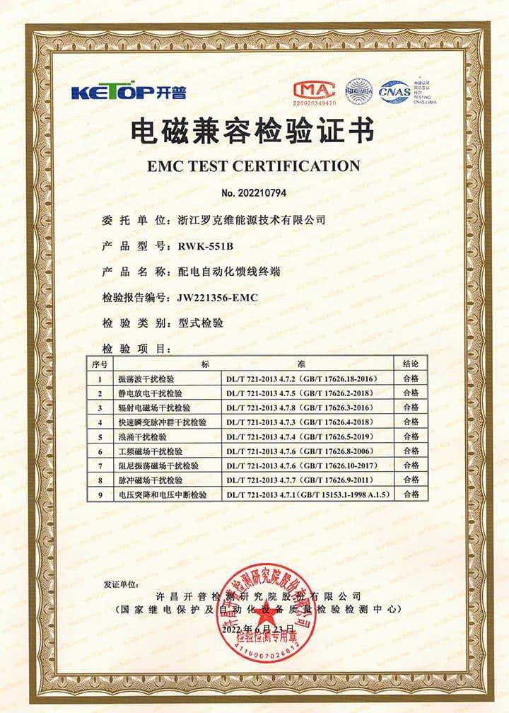
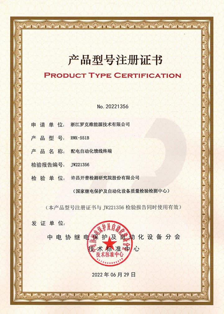
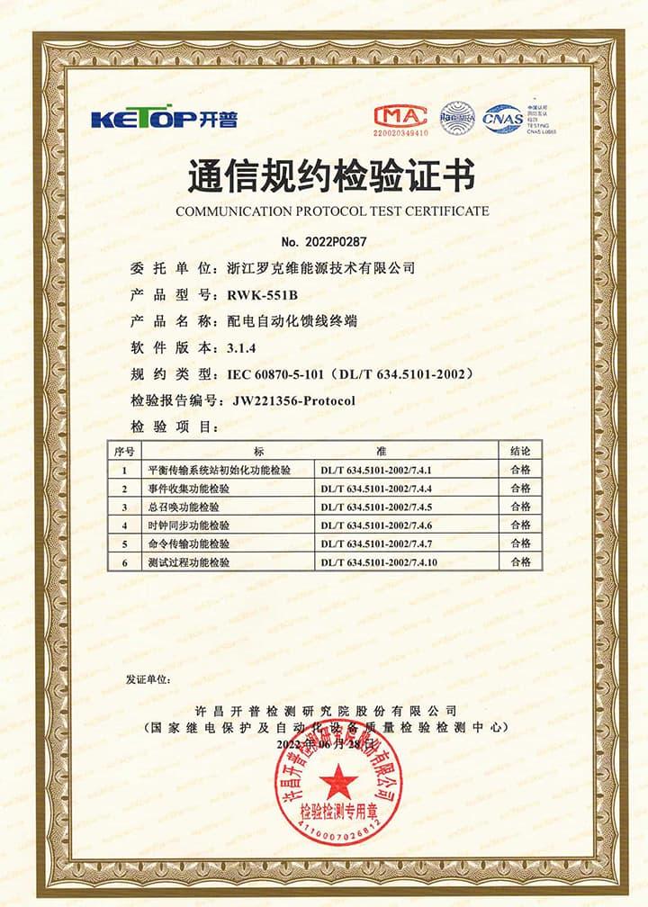
Certifications Recloser Controllers
FAQ for Recloser Controllers
This protective device supports 3-channel serial data communication, which is independent of each other. One of them is RS232, two are RS485, and three are ETH, which can be configured separately. The configuration method is as follows:
- Enter the settings page: Edit → Port → Port1 set;
- Configure communication function on/off: Scroll down and find Comm1 Status set to 1, indicating it is turned on, and 0 indicates it is turned off. The default setting is open;
- Set communication baud rate: According to the baud rate configuration of RTU or protocol converter, the default value is 9600;
- Set communication protocol: There are four protocols to choose from, corresponding to setting 1 as IEC-60870-101, setting 2 as IEC-60870-104, setting 3 as DNP3.0, setting 4 as ModBus RTU, default as IEC-60870-101;
- Set communication balance (only valid for multiple IEC-60870-101): Set 1 to IEC-60870-101 protocol balance mode and 0 to imbalance mode;
- Set the communication source address: Set the value to 1-65535, default value to 1;
- Set the target address for the report: set the value to 0-65535, default value to 1;
- Set active upload: 0 does not actively upload, 1 actively uploads, default value is 1;
- Set remote signaling cycle: set to 1 periodic upload, 0 no upload
- Set the remote signaling cycle time: Set the time in seconds
- Set telemetry cycle: set to 1 periodic upload, 0 no upload
- Set telemetry cycle time: Set the time in seconds
- Save settings: After completing the settings, press the "Enter" key, enter the password 0099 (some models are 0077), press the "Enter" key again, and the screen will prompt "Save successful", indicating that the settings have been saved.
At this point, channel 1 has been established, and channels 2 and 3 are established in the same way as channel 1. At the same time, channel 3 also needs to be configured with network ports. The steps are as follows:
Connect to the computer using an Ethernet cable and access 192.168.0.7 via WEB (the computer's IP address must be 192.168.0.XXX network segment, otherwise it cannot be accessed). After entering the background, select the "Local IP Config" button to set the terminal's DHCP mode, static address, subnet mask, and gateway address; Select the "Serial Port" button in the background, set the output port of the communication protocol in "Local Port number", and set the network port working mode (TCP Server/TCP Client) in "Local Port number". When setting TCP Client, fill in the TCP server address below. At this point, all communication settings have been configured
NOTE: 1. The product has been set to default settings before delivery to meet most usage scenarios. It is not recommended to make modifications or only modify controllable items (such as modifying communication protocols, configuring communication functions on/off, etc.) when it can be used normally
1. How to set the transformation rate
Enter the settings page: Edit → Para; Configure communication function on/off: Scroll down, find CT Rate to set current rate, find VS Rate to set voltage sensor rate, and find PT Rate to set PT rate.
2.How to calculate the transformation ratio coefficient
The transformation ratio of a current transformer is calculated based on the winding rate of the current transformer. For example, a magnet is placed on a copper tube, and the surface of the magnet is wrapped with enameled wire for 400 turns. When a current of 400A passes through the copper tube, an induced current of 1A is generated on the enameled wire. In the industry, the current passing through the copper tube is called the primary current, and the current generated on the enameled wire by electromagnetic induction is called the secondary current. The terminal collects the secondary current and restores the primary current value through a proportional coefficient, which is called the transformation ratio coefficient. Derived from the secondary winding value/primary winding value of the coil. The same applies to voltage transformers.
The rate calculation method of voltage sensors is often based on the voltage division ratio. For example, two resistors with resistance values of 100M and 100K are connected in series between the live wire and the ground wire. When there is a voltage of 10KV on the bus, the voltage at both ends of the two resistors is measured separately, and it is found that they have a 1000:1 relationship, that is, 1000M divided into 9.99kV voltage and 100K divided into 0.01kV voltage. We can restore the original voltage of the bus by collecting the voltage on both sides of the small resistor and multiplying it by the proportional coefficient, The calculation formula is Ubus=U2/1:1000+1, which is the rate value of the voltage sensor.
Three-Section Overcurrent Protection is a coordinated protection scheme widely used in power systems to detect and isolate faults (e.g., short circuits) while ensuring selective tripping. It consists of three stages with distinct operating characteristics based on current magnitude and time delay:
- Instantaneous Overcurrent Protection (Section I)
Function: Responds immediately to severe overcurrents exceeding a high-set threshold (e.g., 5–10 times the rated current).
Purpose: Rapidly clears close-in faults (near the protection device) to prevent equipment damage.
Key Feature: No intentional time delay (operates in milliseconds).
- Time-Delayed Overcurrent Protection (Section II)
Function: Triggers after a predefined short delay (e.g., 0.1–0.5 seconds) for moderate overcurrents (e.g., 2–5 times the rated current).
Purpose: Handles faults farther from the protection device, allowing downstream breakers to clear localized faults first (selectivity).
Coordination: Employs a time-graded scheme—higher fault currents (closer faults) trip faster, while lower currents (remote faults) trip slower.
- Backup Overcurrent Protection (Section III)
Function: Activates after a longer time delay (e.g., several seconds) for low-magnitude overcurrents (e.g., 1.2–2 times the rated current).
Purpose: Serves as a backup for primary protection (Sections I/II) and addresses overloads or persistent faults.
Characteristic: May use an inverse-time curve (trip time decreases as current increases).
Coordination Principle
The three sections work hierarchically:
Section I clears severe faults instantly.
Section II handles moderate faults with short delays, prioritizing system selectivity.
Section III provides backup protection, ensuring reliability if upstream protections fail.
This layered approach minimizes outage scope, balances speed and selectivity, and enhances grid stability.
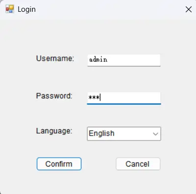
Yes, this device has corresponding upper computer software (only available in windows-X86 version), which can be connected to the terminal through a serial port or network port, enabling fixed parameter configuration and viewing, address configuration for remote signaling, telemetry, and control, viewing of event reports, monitoring of electricity meters, packet capture of communication messages, and simulation of remote control functions.
Sure, this device cannot be upgraded online, but it requires offline firmware version upgrade using a burning device to upgrade more features or fix known bugs. As this device is a customized product, you need to provide us with the device's model number and version number when upgrading. Once we have determined the upgrade plan, we will contact you and provide you with the burning device and firmware upgrade package needed for the upgrade.
When an HV conductor falls on dry terrain (High-impedance fault), standard protection fails to detect micro-currents, causing ignitions. [Solution]: The RWK-35 features 200mA pick-up sensitivity for Sensitive Earth Fault (SEF). [Proof-of-Physics]: Utilizing Scalar Braking algorithms, the controller initiates a trip within milliseconds before thermal energy reaches ignition levels. This capability directly rivals the Eaton Form 7 HiZ protection, serving as a critical safety barrier for bushfire mitigation.
Transformer inrush currents contain significant 2nd harmonic components, often misidentified as short-circuits by basic relays. [Solution]: The internal DSP performs real-time FFT (Fast Fourier Transform). [Physical Action]: If 2nd harmonic content exceeds the 15-20% threshold, the 50/51 protection is temporarily inhibited. This ensures system stability during energization transients without compromising sensitivity to actual internal faults.
Out-of-phase synchronization causes reverse inrush that damages generators. [Implementation]: The RWK-35, paired with external PTs, performs real-time vector comparison between Grid (Us) and DG (Ug) voltages. [Logic Criterion]: Closing is permitted only when Phase Angle Δθ < 10° and Frequency Δf < 0.1Hz. This physical interlocking ensures safe transients for PV plant integration, strictly adhering to grid codes in regions like Colombia.